This page is about using Illustrator features that allow you to turn several objects that are easy to draw into one or more objects that would be much more difficult to draw.
The process is to:
Make several easy-to-draw objects using Illustrator's tools for creating and modifying paths.
Collect the objects into a set with regions that overlap.
Use Illustrator's object combining features to integrate the component objects and especially their overlapping regions into one or more objects that would be difficult and inefficient to draw precisely using the Pen tool.
Illustrator's features for combining objects include:
Pathfinder Operations
Pathfinder Effects
Pathfinder Panel Click Operations
Pathfinder Compound Shape Operations
The Shape Builder tool
Compound Path Operations
Pathfinder Operations
Effects
Panel
Shape
Emulates
1
Add
Unite
Unite
Yes
2
Intersect
Intersect
Intersect
Yes
3
Exclude
Exclude
Exclude
Yes
4
Subtract
Minus Front
Minus Front
Yes
5
Minus Back
Minus Back
Yes
6
Divide
Divide
No
7
Trim
Trim
No
8
Merge
Merge
No
9
Crop
Crop
Yes
10
Outline
Outline
No
11
Hard Mix
Yes
12
Soft Mix...
Yes
13
Trap...
Trap Options
Yes
The Pathfinder operations provide 13 ways of combining overlapping component objects (paths, groups, or text) into a single object or group of objects.
If it were written as a chemical formula, a Pathfinder operation would look like this:
Component Objects + Combining Rule -> Result (Combined Object)
Each operation implements a Combining Rule that specifies (functionally) how the appearance of the Component Paths should be changed into the appearance of the Result, the Combined Object. The names of the operations express (more, or less successfully) how the appearance of the component should be related to the appearance of the Combined Object.
Over the years, Illustrator developed 3 different software modules that implement the combining rules in different ways, have different names, are used differently, and look different in the Layers panel and in the Appearance panel. Therefore, there are three different ways in which you can perform (at least some) of the Pathfinder operations:
Comparison of the 3 Kinds of Pathfinder Operations and Their Representation in the Layers Panel
Pathfinder Panel Operations, which you perform by selecting the component paths and then simply clicking on one of the icons in the Pathfinder panel.
Pathfinder Effect Operations, which you perform by putting the component paths into a Group, selecting the group, and then selecting one of the items from the Effects > Pathfinder menu.
Compound Shape Operations, which you perform by selecting the component paths and then Alt + clicking on one of the 4 icons in the top row of the Pathfinder panel.
Not all of the modules implement all of the Pathfinder operations. The table at the beginning of this section shows how the 3 different ways of performing Pathfinder Operations are related.
The 11 Pathfinder Panel Operations differ from the 13 Pathfinder Effect Operations and the 4 Compound Shape Operations in that the Pathfinder panel click, operations are destructive, whereas the Pathfinder Effects and Compound Shape, Alt + click, operations are nondestructive. Destructive operations replace (and so destroy) the original component paths with new paths whose appearance complies with the combining rule. Nondestructive operations preserve the original component paths in a container. In addition, all 4 Compound Shape Operations and most of the 11 Pathfinder Effects use software that emulates the appearance that the combining rule specifies. The final column of the table shows which Effects emulate the appearance specified by the combining rule.
Comparison of destructive versus non-destructive operations with respect to the fate of the original component paths, their representation in the Layers panel and in the Appearance panel, and the difference between real and virtual paths.
Here are some features that Illustrator's non-destructive operations have in common:
They do not destroy, or even alter, the anchor points, control handles, fills, or strokes of the original component paths, but preserve them inside of a container. The container may have its own software, which generates the combined appearance and where there is a corresponding Pathfinder panel operation, the Effect emulates the Pathfinder panel operation.
The combined appearance and the appearance of the original component paths interact. The features of the appearance depend on how the container interacts with the properties of the component paths. That is, the original shape, color, and relative position of the component paths, plus the combination rule determine how the combined object will look.
You can edit the original component paths inside the container in which they are preserved.
They can create virtual paths. The container software can create appearance features that look like real paths, and that obey the logical appearance rules, but these virtual paths have no anchor points.
They are reversible (i.e., you can undo them). Since non-destructive operations do not change the anchor points, control handles, fills, or strokes of the components you can undo the operation and recover the original component objects.
However, since they have no anchor points or control handles, you cannot directly edit virtual paths. To edit a virtual path, you must first convert the combined appearance into real paths, which you do with Ai's Object > Expand Appearance command. The command replaces the original paths in the container with real paths that look the same. After expanding, the combined appearance of the Effect, is the same as if you had directly applied the corresponding (destructive) Pathfinder effect.
This final point prompts the question: "If the end result of using a nondestructive operation is the same as using a destructive operation, why would you ever use a nondestructive operation?" The value of using a nondestructive operation derives from the fact that creating a design is an iterative process that can require a number of revisions. The fact that you can edit the original component paths means that you can implement new iterations quickly, and you never have to reconstruct the original paths in order to make a minor revision.
Using Pathfinder Operations
Pathfinder Panel Click Operations
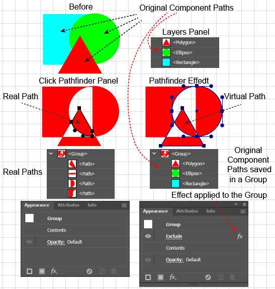
Example of clicking the Pathfinder panel Minus Front button, which yields a simple path that replaces and destroys the original overlapping paths.
To apply a Pathfinder Panel Click Operation in Adobe Illustrator:
Select the overlapping component paths to which you want to apply the operation.
Open the Pathfinder Panel (Window > Pathfinder).
Click one of the 4 Shape Mode buttons in the top row, one of the 6 Pathfinder buttons in the bottom row, or click the panel's hamburger button to drop down the list of options and click the "Trap…" item to launch the Trap dialog box. Ai will apply the Combining rule to the components.
Using the result:
In the Layers panel, Ai will replace (and thereby destroy) the original paths with a single path or with a group of paths.
Editing the original Component Paths is impossible because the paths were destroyed.
Modifying the result is impossible, because the result (the combined path) was not created with a dialog box that can be used to change the combining rule's parameters and because the original paths were not preserved. Therefore, to modify the result, you must recreate the original paths and reapply the effect.
Reversing the result is also impossible because the original paths were replaced with the result paths.
Editing the virtual features of the combined paths is unnecessary because the Pathfinder Click operations do not emulate or preview any features of the result. To edit any feature of the result, you simply select one of the resulting simple paths and edit it in the usual way.
Example of alt + clicking the Pathfinder panel Minus Front button, which preserves the original paths in a Compound Shape container (in the Layers panel) and emulates the appearance of the single path that would result from a simple click on the Minus Front button.
To apply a Pathfinder panel Compound Shape (Alt + Click) operation in Adobe Illustrator:
Select the overlapping component paths to which you want to apply the operation.
Open the Pathfinder Panel (Window > Pathfinder).
Alt + click on one of the 4 Shape Mode buttons in the top row. Ai will create a special type of group that contains the original paths and the Shape Mode software will emulate (preview) an appearance that complies with the applicable combining rule.
Using the result:
In the Layers panel, you will see a (group-like container, labeled Compound Shape) that contains the original components, which are not destroyed in the process.
To edit an original component, simply select the object in the Compound Shape container, move the object, change its color in the Appearance panel, or Direct Select the anchor points or control handles and edit them.
Modifying the effect is not possible because there is no dialog box for any of the 4 Shape Mode operations.
To reverse the operation: go to the Pathfinder panel, click its options menu (hamburger) button, and select "Release Compound Shape."
To edit one of the operation's virtual features (i.e., an emulated feature that is only part of the preview), do the following. Select the Compound Shape container. Execute the Object > Expand Appearance command. Ai will replace the original paths in the Compound Shape container with equivalent looking simple paths and put them in a new Group. In the process, formerly virtual paths will be converted into real paths. The result will look like the result of clicking a Pathfinder panel button. To edit a path (including ones that were formerly virtual,, select a path in the Group and edit it in the usual way. Note, however, that since the original paths are replaced, they are no longer editable and the Expand Appearance command is not reversible.
Pathfinder Effects
Example of applying the Pathfinder Effect > Pathfinder > Subtract (which corresponds to the Pathfinder panel Minus Front operation) to a Group containing the original paths. The original paths remain in the Group, but the Subtract Effect software emulates the appearance of the single path that would result from a simple click on the Minus Front button.
To apply a Pathfinder Effect to several overlapping paths in Adobe Illustrator:
Select the overlapping component paths to which you want to apply the operation.
Group the component paths (Object > Group or Shortcut Ctrl + g).
Go to the Effects > Pathfinder menu and select an effect. Ai will:
Preserve the original paths in a group.
Add a row to the Appearance panel representing the Effect, and
Except for the Divide, Trim, Merge and Outline operations, Ai will emulate (preview) the result of applying the appropriate combining rule. The logic of the combining rules is described below.
Using the result:
In the Layers panel you will see a Group containing the original component objects. When you select that group, you will see in the Appearance panel, a row that represents the Effect, which has a label with the name of the Effect on the left and an fx icon on the right.
To edit the Component Objects: in the Layers panel, simply select the object in the Group, move the object, change its color, in the Appearance panel, or Direct Select the anchor points or control handles and edit them.
To modify the Effect: in the Layers panel, select the Effect's Group; then in the Appearance panel, click the label of the Effect's fx row. Ai will launch the Pathfinder Effect dialog box. Modify the parameters.
To reverse the Effect, go to the Layers panel and select the Group to which you applied the Effect. In the Appearance panel, select the Effect's fx row and click the trash can icon at the bottom of the panel.
To edit one of the Effect's virtual features, do the following: Target the Effect's Group in the Layers panel. Execute the Object > Expand Appearance command. Ai will convert the Effect's emulated appearance to equivalent looking simple paths and in the Layers panel, will replace the original objects with the new paths. To edit a feature, select any path in the Group and edit it in the usual way. Note, however, that since the original paths are replaced, they are no longer editable, and the Expand Appearance command is not reversible.
Pathfinder Operation Rules and Results
While the 3 different Pathfinder methods use different software to implement the Pathfinder operations and have different representations in the Layers panel and in the Appearance panel, the results, in two respects, look the same:
Most of the 13 Pathfinder Effects and all 4 of the Compound Shapes emulate the appearance of the corresponding Pathfinder Panel operation. That is, when you have the Preview checkbox checked in the Effect dialog box, the Effect gives you a preview of the corresponding Pathfinder panel operation.
After you expand the appearance of a Pathfinder Effect or a Compound Shape it will look like the corresponding Pathfinder operation.
Furthermore, at a functional level, whenever the 3 different methods implement the same operation (e.g. Intersect or Exclude) they follow the same combining rule. This section illustrates the logic of the combining rules. In what follows, I will use the term path in quotes ("path") to refer to a path that may be either real or virtual.
Recall, however, that the Pathfinder Divide, Trim, Merge and Outline Effects do not emulate (preview) the appearance of the corresponding Pathfinder Panel operations. Therefore, when you apply one of these Effects, they appear to do nothing, even if you have checked the Preview button in the Effects dialog box. Nonetheless, after you execute the Expand Appearance command on the Effect, it will look like the corresponding Pathfinder Panel operation. The following descriptions (and the above table) explicitly note which Effects emulate (preview) the corresponding Pathfinder panel operations and which do not.
Combining Rules
Schematic showing how Illustrator might analyze Faces and Edges when combining 3 overlapping Component Paths.
The combining rules work by analyzing the overlapping regions of the original Component Paths into an equivalent set of imaginary non-overlapping regions, which are called Faces. As illustrated in the accompanying figure, the boundaries between faces are called Edges. So, a face is a closed area bounded by edges, but with no edges inside it.
The combining rules do not really break up the original paths into these faces and edges, they merely work out a way of partitioning the overlapping regions, of the original Components into mutually exclusive regions (faces) that together would cover the original paths. As illustrated in the accompanying figure, some of the overlapping regions of the original paths may contain the same Face, and some Faces may belong to only one of the original component paths, while others may belong to several component paths.,
The operation of the combining rules may depend upon the:
Relative location of the original Component Objects. For example, a rule may create different types of objects depending upon whether or not one path completely contains another path.
Stacking order of the overlapping components that contain the face. For example, in many rules, the color of a face in the result becomes the color of the face as it was in the top component to which it belonged.
Number of original overlapping components that contain a face. For example, in the result of the Exclude operation, which faces are filled and which are transparent depends upon whether the face belongs to an even or odd number of the original components.
Color of the faces (belonging to the different Component paths) that are involved in the operation. For example, for some rules, Ai merges faces of the same color.
Add Effect (Unite) Operation
Expanded Result of an Add (Unite) Operation
This operation will unite all the faces into a single path. It will:
Find the perimeter of all the faces.
Make the perimeter the "path", of the combined object, and
Give it the fill of the topmost component in the stacking order.
The Add Effect emulates the appearance of the corresponding Pathfinder panel Unite operation.
Unite is one of the 3 most frequently used Pathfinder operations and it is equivalent to merging all the faces with the Shape Builder tool.
Intersect
Expanded Result of an Intersect Operation
This operation will find the face that belongs to all the component objects, make that face's outline the "path" of the combined object, and give it the fill of the topmost component object.
The Intersect Effect emulates the appearance of the corresponding Pathfinder panel Intersect operation.
Exclude
Expanded Result of an Exclude Operation
This operation will find all the faces where all component objects overlap, and use the Odd – Even Rule to determine which faces will be included or deleted from the result. That is:
Where a face belongs to an even number of original component objects, make that face a transparent area.
Where a face belongs to an odd number of original component objects, make that face a "path" and fill it with the color of the topmost component.
The Exclude Effect emulates the appearance of the corresponding Pathfinder panel Exclude operation.
Subtract (Minus Front)
Expanded Result of an Exclude (Minus Front) Operation
This operation subtracts away from the back component any faces that belong to components that are in front of it, i.e., higher up in the stacking order.
That is, it will:
Find any face that belongs to an original component that is above the bottom component in the stacking order and delete it from all the components.
Make the remaining face (or faces) the "path" of the resulting object and give it the fill of the bottom component object.
The Subtract Effect emulates the appearance of the corresponding Pathfinder panel Minus Front operation.
Minus Front is one of the 3 most frequently used Pathfinder operations and it is equivalent to Alt + dragging across all the front faces with the Shape Builder tool.
Minus Back
Expanded Result of a Minus Back Operation
This operation subtracts away from the front component any faces that belong to components that are in back of it, i.e., lower in the stacking order
That is, it will:
Find any face that belongs to an original component that is below the top component in the stacking order and delete it from all the components.
Make the remaining face (or faces) the "path" of the resulting object and give it the fill of the top component object.
The Minus Back Effect emulates the appearance of the corresponding Pathfinder panel Minus Back operation.
Divide
Expanded Result of a Divide Operation.
To better demonstrate the result, its faces have been separated.
This operation will:
Find all the faces in the set of original component objects,
Make each face into an independent "path," and fill it with the color of the topmost component to which the face belongs.
In both the Pathfinder Effect Dialog box and in the Pathfinder panel Options menu, you can check the "Divide and Outline Will Remove Unpainted Artwork" checkbox to tell the software to skip any faces that are not filled.
The Divide Effect does NOT emulate the appearance of the corresponding Pathfinder panel Divide operation. Therefore, to be able to see any result from the Divide Effect, you must execute the Expand Appearance command.
Divide is one of the 3 most frequently used Pathfinder operations and it is equivalent to clicking (isolating) all the faces with the Shape Builder tool.
Trim
Expanded Result of an Trim Operation.
To better demonstrate the result, its faces have been separated.
This operation will trim away any part of each overlapping component that is hidden by another component.
That is, it will:
Remove any face from an original component if the face is hidden under the corresponding face of another component that is higher up in the stacking order.
Remove the stroke from the topmost component object.
The Trim Effect does NOT emulate the appearance of the corresponding Pathfinder panel Trim operation. Therefore, to be able to see any result from the Trim Effect, you must execute the Expand Appearance command.
Merge
Expanded Result of an Merge Operation
Like the Trim operation, the Merge operation trims away any part of each overlapping component that is hidden by another component, however, it will merge overlapping areas of the same color. That is, it will:
Remove a face from an original component if the face is hidden under the corresponding face of another component that is higher up in the stacking order.
Merge (i.e., add or unite) all the faces that are the same color).
Remove the stroke from the topmost component object.
The Merge Effect does NOT emulate the appearance of the corresponding Pathfinder panel Merge operation. Therefore, to be able to see any result from the Merge Effect, you must execute the Expand Appearance command.
Crop
Expanded Result of an Crop Operation
This operation will:
Delete the faces that belong to any component unless they also belong to (are inside of) the topmost original component.
For the remaining faces, retain the color of the component to which it belonged.
The result looks like the topmost component was used as a clipping mask.
The Crop Effect emulates the appearance of the corresponding Pathfinder panel Crop operation.
Outline
Expanded Result of an Outline Operation
This operation will:
Find all the edges.
Make each edge into a single path with no fill or stroke.
In both the Pathfinder Effect Dialog box and in the Pathfinder panel Options menu, you can check the "Divide and Outline Will Remove Unpainted Artwork" checkbox to tell the software to skip any edges that do not bound a filled face.
The Outline Effect does NOT emulate the appearance of the corresponding Pathfinder panel Outline operation. Therefore, to be able to see any result from the Outline Effect, you must execute the Expand Appearance command.
Hard Mix Effect
Expanded Result of an Hard Mix Operation
This operation will:
In each face that belongs to several original components, determine its color (i.e., the percentage values for each of the 4 primary colors: cyan, magenta, yellow, and black) by taking the highest percentage for each primary color value that is found in any of the original components to which the face belongs.
Remove the strokes from all the objects in the group.
The Illustrator documentation uses the following example for a case where there are only two overlapping original components: Component 1 Color: (20% ,66%, 40%, 0%) Component 2 Color: (40%, 20%, 30%, 10%) Overlapping Face Color: (40%, 66%, 40%, 10%)
There is no corresponding Pathfinder panel operation for the Hard Mix Effect.
Soft Mix Effect
Expanded Result of a Soft Mix Operation
This operation will:
In each face that belongs to several original components, determine its color (i.e., the percentage values for each of the 4 primary colors: cyan, magenta, yellow, and black) by mixing the primary colors by the percentage that is specified in the Pathfinder Effect Dialog Box > Soft Mix Settings field.
Remove the strokes from all the objects in the group.
In the configuration shown in the accompanying figure, you can see that the coloring process will determine a different color for each face in the original component paths.
There is no corresponding Pathfinder panel operation for the Soft Mix Effect.
Trap
Expanded Result of a Trim Operation
A Trap is a narrow, filled path of mixed color between two contiguous regions of different colors. Usually the lighter color is printed on top of and blends into (i.e., is overprinted into) the darker color. Designers may create a Trap to prepare art for the printer. The thin band of mixed color (which appears to trap the lighter colored region into the darker colored region) conceals differences in the registration of different printing plates and prevents minor mis-registration from leaving a white line between the colored regions.
Pathfinder Panel Trap
To create a Trap with the Pathfinder panel in Adobe Illustrator:
Select the paths between which you want to create a Trap.
Go to the Pathfinder panel, and in the upper right corner, click the hamburger button to twirl down the Options menu.
In the menu, select Trap. Ai will display the Pathfinder Trap dialog box.
create a Trap Effect via the Effect menu in Adobe Illustrator:
Select the paths between which you want to create a Trap.
Group the regions by executing the Object > Group (Ctrl + g) command. Ai will create a Group in the Layers panel.
Target the Group and execute the Effect > Pathfinder > Trap command. Ai will display the Pathfinder Options dialog box with the Operation field set to Trap and the Trap Settings fields active.
Thickness (in points): the width of the Trap path.
Height/Width percentage: the ratio between the thickness of the Trap on vertical vs. horizontal paths. Setting the ratio to greater than 100%, makes Ai keep the vertical value as specified in the Thickness field, but it will increase the Trap on horizontal lines by the specified proportion. Setting the ratio to less than 100%, makes Ai still keep the vertical value as specified in the Thickness field, but it will decrease the Trap on horizontal lines by the specified proportion. This setting is useful when paper may stretch more (and therefore make mis-registration more likely) in one direction than in another.
Tint Reduction percentage: reduces the tint of the lighter color. (A tint is a color that is lightened by adding white. This setting is useful when making a Trap between two light colors where the Trap path might show through the darker color.)
Traps with Process Color checkbox: tells Ai to construct the trap between spot colors with process colors, make the Trap mimic the lighter of the spot colors, and overprint it.
Reverse Traps checkbox: tells Ai to emulate a printing process where the darker color is printed on top of the lighter color so that the two inks blend on the paper. Usually the lighter color is printed on top of and blends into (i.e., is overprinted into) the darker color.
Trap Effects have two Advanced Options:
Precision (in points): the margin of error that Ai should maintain when calculating the Trap path.
Remove Redundant Points checkbox: tells Ai to remove non-functional points from the Trap Path.
Shape Builder
Schematic diagram of how Ai analyzes two overlapping paths into 7 faces and 12 edges.
Like the Pathfinder Operations, the Shape Builder tool combines overlapping paths, and it works by analyzing the overlapping regions into an equivalent set of imaginary non-overlapping regions, which are called faces. As illustrated in the accompanying figure, a boundary between faces is called an edge. So, a face is a closed area bounded by edges, but with no edges inside it. The tool does not really break up the original paths into these faces and edges, it merely works out a way of partitioning the original overlapping regions, into mutually exclusive regions (faces) that together would cover the original paths.
When you use the Shape Builder tool, it shows you the faces and edges that cover the original overlapping paths, and provides command gestures and keystrokes that allow you to isolate a single face from the original paths and to merge or delete faces. The tool provides a visual and more flexible alternative to using the Shape Mode tools (in the Pathfinder Panel).
The remaining articles in this section describe how to do Shape Builder operations.
Delete Faces Using Shape Builder
When Shape Builder deletes a face, it reconstructs the original overlapping paths around the deleted shape.
To erase faces from selected overlapping paths using Shape Builder in Adobe Illustrator:
Select the overlapping paths.
Get the Shape Builder tool.
Alt + Click or Alt +click + drag through the faces that you want to remove. Ai will remove them and then unite the other faces so that they look like the original overlapping paths, but with the isolated face cut out.
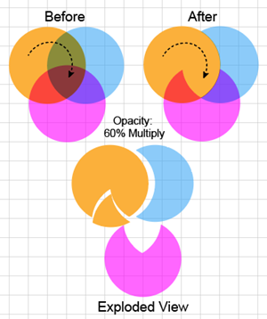
The accompanying illustration shows an example with 3 overlapping paths. In the Before figure, in order to show all the overlapping regions, each circle's Opacity is set to 60% and its blending mode set to Multiply. Ai will analyze these overlapping regions into faces. When one face is deleted, not only does Ai delete that face, but it also reconstructs the original overlapping circles with the deleted face cut out. The Exploded View shows the structure of the reconstructed circles by moving them apart from one another so that the Multiply blend mode does not show the overlapping regions and thereby hide the form of the reconstructed areas.
Alt +click + dragging or Alt + clicking several times with the Shape Builder is equivalent to the Pathfinder Subtract (Minus Front) operation, which may still be a useful alternative to the Shape Builder when there are many components.
Isolate a Face Using Shape Builder
When Shape Builder isolates a face, it not only makes the face into a new path, but it also reconstructs the original overlapping paths, minus the area that was occupied by the isolated face. Thus, where there were 3 paths, after the isolation operation, there are 4 paths.
You can isolate a face from the original set of overlapping paths. The isolated face becomes an independent path (an island) and its shape is cut out of the original overlapping paths of which it was a part.
To isolate a face from a set of overlapping paths using Shape Builder in Adobe Illustrator:
Select the overlapping component paths.
Get the Shape Builder tool. Ai will analyze the shape into its component faces and edges. As you hover over the faces with the mouse, Ai will highlight them with a gray mesh.
Click the face that you want to isolate. Ai will add the anchor points necessary to make the face into a closed path, and will unite the other faces so that they look like the original overlapping paths, but with the isolated face cut out.
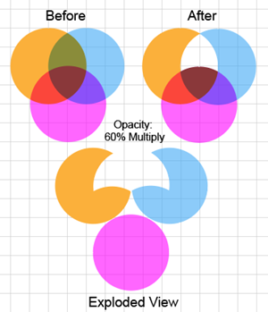
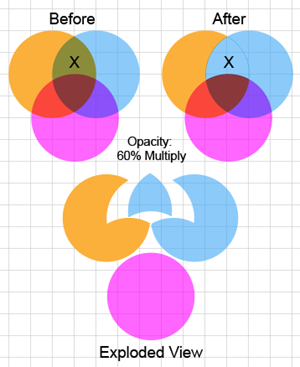
The accompanying illustration shows an example with 3 overlapping paths. In the Before figure, in order to show all the overlapping regions, each circle's Opacity is set to 60% and its blending mode set to Multiply. Ai will analyze these overlapping regions into faces. When you click on a face (marked with a X in this example) to isolate it, not only does Ai make the face into a standalone closed path, but it also reconstructs the original overlapping circles with the deleted face cut out. In the After figure, Ai has made the isolated face blue, because you clicked on the blue circle, which was on top of the orange circle. The Exploded View shows the structure of the reconstructed circles by moving them apart from one another so that the Multiply blend mode does not show the overlapping regions and thereby hide the form of the reconstructed areas.
Clicking on faces to isolate them is equivalent to the Pathfinder Divide operation, which may still be a useful alternative to the Shape Builder when there are many components.
Merge Faces Using Shape Builder
In this example, the arrows show where the cursor was dragged to merge the faces. The Exploded View shows the result of the merge, and the paths where Ai has reconstructed as much of the original paths as possible with the merged path cut out.
To merge faces of overlapping paths using Shape Builder in Adobe Illustrator:
Select the original overlapping paths.
Get the Shape Builder tool. Ai will analyze the overlapping paths into their component faces and edges. As you hover over the faces with the mouse, Ai will highlight them with a gray mesh.
To unite two or more faces, first identify them to the Shape Builder). Either: (A) Click + drag across their boundaries (but do not release the mouse button), or (B) Shift + drag to create a marquee that covers the faces. As you identify the faces, Ai will extend the gray mesh highlight to cover all of them.
Release the mouse button. Ai will merge the highlighted faces. That is, it will convert the highlighted faces into a closed path and if necessary, create additional anchor points to create closed paths to represent the remaining, unmerged faces. The Layers panel shows the remaining paths. Some of the new closed paths may contain nested paths. To edit the nested paths, you must double-click them to enter Isolation Mode.
Ordinarily Ai takes the style (fill and stroke) of the merged path from the face where you started the Click + drag operation. You can override Ai's choice of the fill color by using the Pick Color From option in the Shape Builder Options dialog box, which you access by double-clicking the Shape Builder Tool
Merge is equivalent to the Pathfinder Add (Unite) operation, which may still a be useful alternative to the Shape Builder when there are many components.
Setting Shape Builder Tool Options
To set the Shape Builder tool's options in Adobe Illustrator:
In the Tools panel, double click the Shape Builder tool icon . Ai displays the Shape Builder Tool Options panel.
In the panel, select an option.
Shape Builder Options
Gap Detection
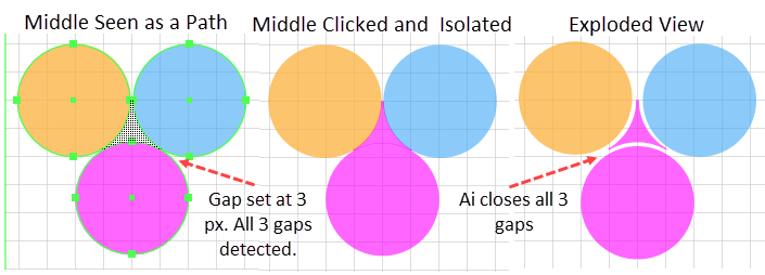
Example showing that with the Gap Detection length set to 3 px, in spite of the gaps, Shape Builder analyzes the area between the 3 circles as a Face. As shown in the Exploded view, if you click the area, Ai isolates the central Face and adds the necessary lines to close its gaps.
The Gap Detection field defines a length that Ai will use to target gaps in and between paths and deal with them in its process of building shapes. Ai will:
Detect (find and track) all the gaps of approximately the specified length. Ai will ignore Gaps of less than or more than the specified amount.
Consider the detected gaps to be part of some path when analyzing the Faces and displaying them (with the mesh overlay) in the Shape Builder's user interface.
After you have used the Shape Builder tool to isolate, merge, or delete Faces, Ai will automatically add anchor points and control handles to close the gaps in the resulting artwork.
Consider Open Filled Path as Closed
Example showing that with this option enabled, Shape Builder analyzes the orange open path as a Face and when clicked, Ai will isolate it as an independent, closed path.
This option tells the Shape Builder tool to consider open paths as closed when it is analyzing the selected overlapping paths into faces. Then when you mouse over an open path with the Shape Builder tool, it will show you a mesh overlay, and if you click on the open path Ai will isolate the path and close it.
In Merge Mode, Clicking the Stroke Splits the Path
Example of dividing a circle by clicking on the edge that forms its left-most border.
Setting this option changes how the Shape Builder tool behaves when you are clicking and dragging with the tool to merge paths (but not when you are Alt + clicking to delete faces). With this option set, when you hover over an edge, the cursor will change its modifier and provided that you have the Highlight option set will highlight the edge. Then when you click on the edge Ai will convert the portion of the path that is under the edge into an open path.
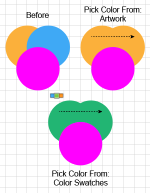
Pick Color From
The Pick Color From dropdown box, provides only two alternative settings:
Artwork, and
Color Swatches
The Artwork option is the default. With this setting, whenever you perform an operation, Ai will try to fill and stroke the result from the color of the original overlapping paths. For example, if you merge two faces, the resulting merged path will have the stroke and fill of the face where you started the merge.
If Ai cannot conclusively determine the style (e.g. when the face is part of several shapes), it will use the style of the face where the mouse is released. If it still cannot guess the style, it uses the style of the top face in the stacking order.
Coloring while merging with the "Pick Color From" dropdown option set to "Color Swatches"
The Color Swatches option allows you to select the color from the Swatches panel. This option also provides a Color Swatches Preview checkbox which, when checked, enhances the cursor with a widget that displays 3 boxes that represent possible swatches. The center swatch in the cursor widget is the one that Ai will apply to a merged face.
Clicking a swatch in the Swatches panel loads the swatch into the center cursor box of the widget and loads the swatches on either side of the selected swatch in the other two cursor swatches. Clicking arrow-keys pages through the swatches in the Swatches panel and loads them into the cursor widget.
With the Color Swatches and Color Swatches Preview options selected, you can use an arrow key to select a color, and then when you use the tool to isolate a face or merge faces, Ai will color the result with the selected color.
Selection
The Selection area in the Shape Builder Tool Options dialog provides two radio buttons that affect the kind of track that you draw with the cursor to tell the Shape Builder which Faces to merge. Selecting:
Straight Line constrains the track to a straight line.
Free Form (the default) allows you to draw a free-form track.
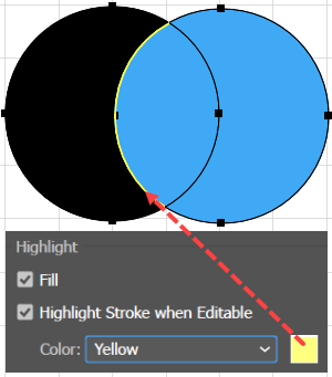
Highlight
The Highlight Stroke when Editable option and its Color setting allows you to get a clear signal confirming that you have successfully selected an Edge.
The Highlight area provides two checkboxes:
Fill (the default), which when checked, tells Ai to highlight the to-be-merged areas when you mouse over them with the Shape Buildertool. Unchecking toggles highlighting off.
Highlight Stroke When Editable, which when checked tells Ai to highlight the strokes that you can edit, and displays a dropdown box that allows you to pick the color of the highlight.
Compound Paths
Objects with holes are represented as Compound Paths
Compound Paths are objects (i.e., software modules) that are designed to represent closed paths that have holes. A Compound Path is so called because it is a compound of an outer path that defines the perimeter and one or more inner paths that define negative spaces (holes) in the interior of the outer path. In contrast to Compound Shapes and Pathfinder Effects, which are newer, Illustrator-specific features, the Compound Path feature is a legacy technology that is supported by most vector drawing packages.
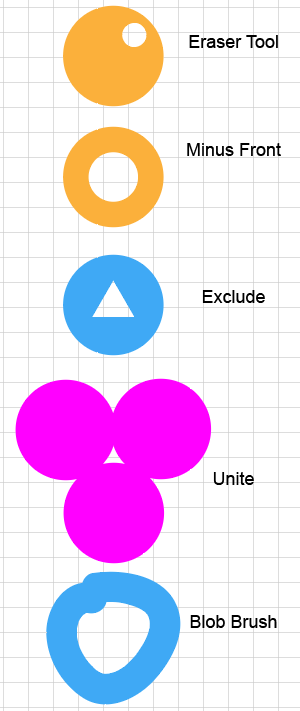
Almost any procedure that creates a hole inside a closed path creates a Compound Path. You can, for example:
Click with the Eraser tool to punch a hole in a shape.
Place one shape on top of and inside the boundary of another shape, select the shapes and either:
Go to the Pathfinder panel and click the Minus Front button, or
Go to the Pathfinder panel and click the Exclude button.
Create three or more shapes that connect with one another but leave a hole in the middle, select the shapes, and go to the Pathfinder panel and click the Unite button.
With the Blob Brush tool, draw a figure that contains a hole.
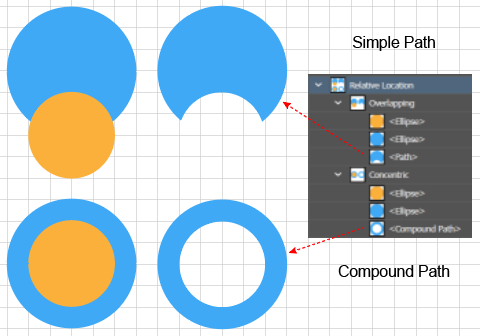
The Minus Front command can produce a simple path or a Compound path depending on the relative location of the objects being combined
The above examples illustrate that the relative position of the original Component Paths can be decisive. However, more is true. The same command can produce different results depending on the relative location of the original Component Paths. Consider using the Pathfinder panel Minus Front command on the two configurations illustrated in the accompanying figure. When Minus Front is applied to overlapping circles, you get a simple path with a bite taken out of it, but when applied to concentric circles, you get a Compound Path.
There is one exception to the above point. Using the Compound Path Make command always produces a Compound Path Object (as you can see clearly in the Layers panel, even if the relative location of the original Component Objects do not define an inner path and the command does not produce a hole.
Creating a Compound Path with Compound Path Make
To create a Compound Path from two or more overlapping closed paths in Adobe Illustrator:
Select the component paths.
Execute the Object > Compound Path > Make command. Ai will combine the component paths into a single object (as opposed to a Group), and in the Layers panel give it the default label "<Compound Path>."
Illustrator's Object > Compound Path > Make facility does two things:
If the command is applied to two or more paths that overlap, it excludes the overlapping region from the resulting Compound Path.
Combines several of the component paths together to create a single path in which the positions of the component paths relative to one another remain fixed.
In fact, you can use Illustrator's Object > Compound Path > Make facility to combine several paths into a single rigid object even if they do not even overlap, much less define a hole. Thus, while all paths with a hole are represented with Compound Paths, perversely, not all Compound Paths must have a hole.
When two overlapping paths are converted into a Compound Path the result is similar to the result of clicking the Pathfinder panel > Shape Mode area > Exclude button. However, there are two differences:
The Make method uses the fill of the bottom object, whereas the Exclude method uses the fill of the topmost object to determine the Compound Path's fill.
The Make method uses the non-zero winding rule, but Exclude uses the odd-even rule to determine the distribution of fills in the areas where the components overlap.
Once you make the original component paths into a Compound Path, you no longer have direct access to them. However, you can enter the Compound Path object by clicking repeatedly on it. This will cause Ai to enter Isolation Mode, as though the Compound Path were a Group. In addition, you can release the components from the Compound Path object.
Releasing a Compound Path
Releasing a Compound Path is an approximate inverse of creating a compound path, and it works even if the Compound path was not created with the Make command.
The inverse is only approximate, because while creating a Compound path does not completely destroy the original component paths, neither are they completely preserved and so, they can only be approximately recovered. For example, the original colors are nearly always lost.
Nonetheless, except for paths with holes that were created by a Unite operation, the Release command will recover much of the original paths. Consequently, to edit the original components of a Compound path, you must release the path, reconstruct (e.g. recolor) the original components from the recovered bits, edit the reconstructed components, and then recreate the compound path.
To release a Compound Path in Adobe Illustrator:
Select the Compound Path.
Object > Compound Path > Release. Ai will return the original component objects. For example, if you started with two Ellipses (i.e., Live Shapes), after releasing the Compound Path, you will have two Ellipses, not two normal paths. However, the fills will not return to their former color.
Note: The Object > Expand Appearance command cannot be applied (is grayed out for) Compound Paths. The Object > Expand command can be applied to a Compound Path Object, but it only results in a Group that contains two compound paths, one for the Fill and one for the Stroke.
Illustrator Pathfinder Effects by Cheryl Graham at Envato Tuts+ Cheryl Graham demonstrates Illustrator's live Pathfinder Effects. This is part 2 of the VectorTuts+ tutorial.