Adobe Illustrator Smart Notes

Live Effects

Overview

The Nature of Effects

Effects (also called Live Effects) are functions that you can apply to objects to give them appearances, i.e., virtual properties, that go beyond the real properties that the objects have as a result of their, anchor points, control handles, fills, and strokes. Live effects have the advantage that: they are non-destructive (i.e., the real properties remain editable), their virtual properties remain modifiable (via dialog boxes), and they are reversible.

Live Effects are similar to other Live technologies, such as Live Corner Widgets, Live Shapes, and Compound Shapes. All these "Live" technologies preserve the objects to which they are applied, so that if you need to change their virtual or real properties you can modify or edit them, rather than having to recreate them.

You can apply Live Effects to an entire object (path, group, or layer), individual fills, or individual strokes.

Here are the key points:

  • Each Effect has its own distinctive, virtual appearance properties and its own dialog box that you use to set the parameters that control the Effect's virtual properties.
  • Whenever you give an object an Effect, Ai adds an fx row to the Appearance panel. The row has an fx icon and the Effect name. You can click on the fx row to open the dialog box and modify the parameters.
  • Effects are dynamically modifiable (but not directly editable with the normal path editing tools). You can modify an Effect's virtual properties at any time by clicking the Effect's row in the Appearance panel. That will launch the Effect's dialog box, from which you can change its virtual properties.
  • Effects are non-destructive and reversible. Effects do not add or change the anchor points, control handles, or fills and strokes of the objects to which they are applied. The result of applying an Effect to an object, may look similar to the result that you would get by using one of the Toolbar tools, but whereas; tools modify anchor points and control handles, Effects do not.
  • The non-destructive nature of Effects mean that their real properties remain editable with normal path editing tools. Effects' virtual properties are built on top of the object's real properties. Furthermore, often editing an object's real properties (position, shape, fills, strokes, color etc.) will change some of the Effect's virtual properties in a similar way, and so give the Effect additional flexibility.
  • However, an object's virtual properties are not editable with normal path editing tools (they are only modifiable via the Effect's dialog box). To edit an appearance, you must first convert it into real paths, which you can do with Ai's Expand Appearance command. When you Expand an Effect's appearance properties into real paths, you can edit them with the normal path tools, but since the new object no longer has the effect, after expansion, the virtual properties can no longer be modified via the Effect's dialog box.

Applying an Effect

Not all Live Effects are applicable to all types of objects, but you can apply some Effects to a variety of objects: layers, groups, paths, and within a particular path to its individual fills, or strokes. In addition, there are many kinds of Live Effects, which vary greatly in complexity, but applying an effect is similar for all of them.

To apply an Effect in Adobe Illustrator:

  1. In the Layers panel target the object so that the object appears in the Appearance panel.
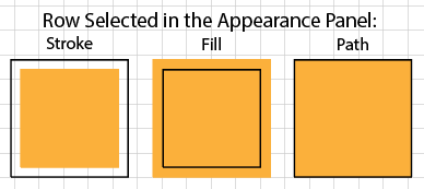
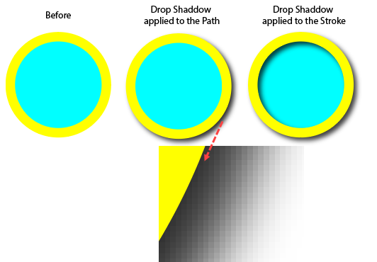
  2. If you want to apply the effect to an attribute (fill or stroke), target it in the Appearance panel.
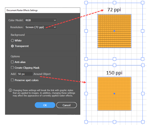
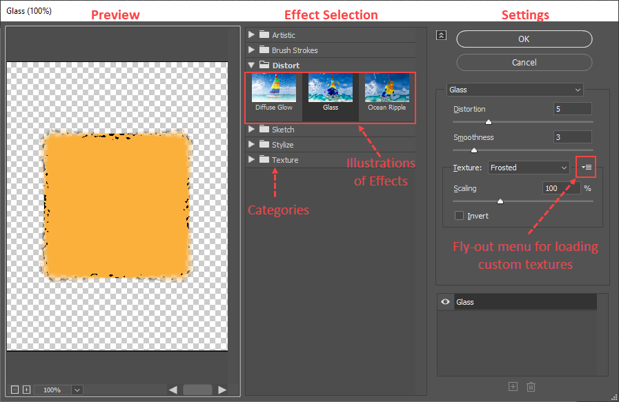
  3. Open the Effect menu and choose one of the illustrator Effects. Ai will open a dialog box.
  4. Set the parameters in the dialog box and click OK.  Ai will represent the effect in the Appearance panel by doing one of the following:
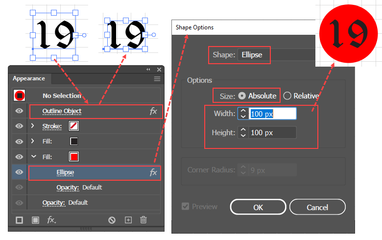
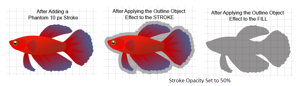
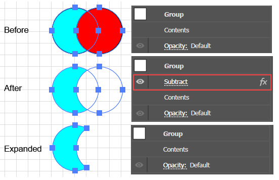
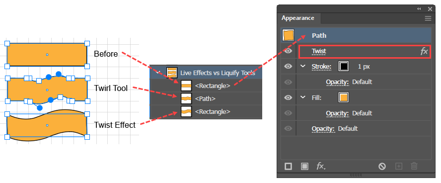
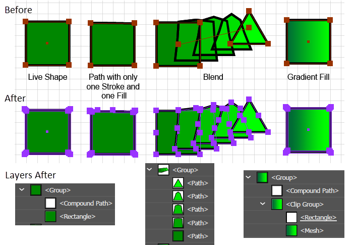
    • If you have applied the Effect to the entire object, Ai will add a new row to the bottom of the Appearance panel, below all the rows that have down arrows and represent the object's fills and strokes. The new row will show the name of the Effect on the left side and a small fx icon on the right side
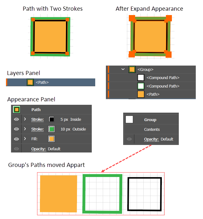
    • If you have applied the Effect to a particular fill or stroke, Ai will add a new row beneath the row of the fill or stroke in the Appearance panel. To see the new row, you may have to click the row's disclosure arrow. The new row will show the name of the Effect on the left side and a small fx icon on the right side.
Example: How Applying Effects Differs Editing Paths with Tools
Example comparing using the Twirl tool versus applying the Twist Effect

Here is a concrete example that illustrates how Effects differ from basic open or closed paths, suppose that you start with a Rectangle, copy it twice, and then: (A) modify one copy with the Twirl tool, and apply the Twist Effect to the other copy. You would notice the following differences:

  • You can apply the Twist tool to a portion of the rectangle, but the Twist Effect always applies to the entire rectangle or to the entirety of one of its fills or strokes.
  • If you Direct Select the twisted rectangles, so that (as illustrated in the accompanying figure), you can see the anchor points, you can notice three key differences:
    • The Twist Tool version has many extra anchor points, but the Twist Effect version has none. In fact, you can still see the original shape.
    • In the Layers panel, the Twist tool version has ceased to be a rectangle (a Live Shape) and is now simply a Path, reflecting the fact that the tool has added anchor points. In contrast, the Twist Effect is still a Rectangle.
    • In the Appearance Panel, the Twist Tool version has only the normal fill and stroke rows, but the Twist Effect version has another row that is labeled "Twist" and sports an fx Icon.

Modifying an Effect

To change the parameters that define an Effect's virtual properties in Adobe Illustrator:

  1. Select the object In the Layers panel or in the Artboard. Ai will then display the object's appearance attributes (including its Effects) in the Appearance panel. Each Effect is marked by a row with the name of the Effect and an fx icon.
  2. In the appearance panel, click the name of the Effect that you want to modify. Ai will open the dialog box for the Effect.
  3. In the dialog modify the parameters that define the virtual properties that you want to change, and click OK.

Reversing (Undoing) an Effect

In Adobe Illustrator, to undo an object's effect so that you can edit the original object to which the Effect was applied:

  1. Select the object. Ai will then display the object's appearance attributes (including its Effects) in the Appearance panel. Each row representing an Effect is marked with an fx icon.
  2. In the Appearance panel, select the row that represents the Effect that you want to undo, and delete it by clicking the Trashcan Icon.

Expanding Effects

Illustration of The Process of Creating and then Expanding an Object's Appearance
Creating and then Expanding an object's Effect in order to edit its depth-portraying (read from bottom to top).

Expanding an object's Effect is a process of converting it into a collection of simple paths each of which can be edited, in detail, with path tools.

Expanding an object with an Effect can be necessary if you want to have a document printed or send it to another program that does not understand the Portable Document Format, (PDF (now ISO 32000), but more importantly, expanding an object with an effect in order to make its virtual properties editable with normal editing tools is a normal part of working with Effects.

For example, the accompanying figure shows what happens when you apply an Extrude and Bevel Effect to a square (bottom figure labeled Before); you get the appearance of a cube (Effect Applied). In the Effect's dialog box, you can control the apparent depth, rotation, perspective, etc., but you cannot change the individual faces.  However, you can use the Expand Appearance command to convert the virtual surfaces (those that involve the Z-axis and give the cube its depth) into real paths that you can select in the Layers panel, target in the Appearance panel, and edit with normal path editing tools. The top frame of the figure shows that the individual faces have been edited, by changing their color and moving them apart.

Of course, expanding an objects appearance has a downside. Since, as you can see from the snapshots of the Layers and the Appearance panels, the conversion process has replaced the original square and its cubic appearance with simple paths, you can no longer use the dialog box to modify the parameters of the apparent cube, nor can you undo the Effect and modify the square.

Example of path with two Strokes that can be expanded with the Expand Appearance command

The figure also illustrates a theme in the working of the Expand Appearance command. The result is not just a bunch of paths. The paths are organized with Groups. There is always one master container Group, and inside of it are groups that mirror the structure of the appearance. In this case, there is a Group containing three Groups, each of which represents a face of the cube, and finally each group contains a single path.

Note that (as illustrated in the accompanying figure) the Expand Appearance command is applicable to many kinds of objects that have appearance attributes that go beyond what can be achieved by basic paths, with a single fill and stroke.  These include not just Effects but also, Compound Shapes, paths with multiple fills or strokes, and paths that have a Width Profile.

Expand vs Expand Appearance

In addition to the Object > Expand Appearance command, there is also an Object > Expand command. Which prompts the question "how are they different"? The purpose of this section is to answer that question.

In a general sense, both Expand commands do the same thing (i.e., replace a complex, virtual object with a group that looks like the original object, but that contains only simple, real paths. However, the two commands apply to different settings. Nonetheless, it is not necessary to choose between the two commands, because only the applicable command will be active.

Illustration of objects to which the Expand command applies.

The Expand Appearance command works on objects that have enhanced appearances. These include:

  • Effects (created via the Effect menu)
  • Compound Shapes (created by Alt-clicking a Shape Mode button in the Pathfinder panel).
  • Paths with multiple fills or strokes (created in the Appearance panel),
  • Paths that have a Width Profile (created via the Appearance panel's Stroke sub-menu).

In contrast, the Expand command works on objects that have a basic appearance. These include:

  • Basic Paths and Live Shapes (i.e., ones that have only one fill and one stroke,
  • Blends, and
  • Paths with a Gradient Fill. 

If you expand a Live Shape or a path, you get a group containing two simple paths (one for the fill and one for the stroke), both of which will have only fills. The path for the Stroke will become a Compound Path because as a stand-alone filled path, it has a hole. Expanding a Blend (as illustrated in the accompanying figure), yields a group of the individual steps in the blend. In addition, the Expand dialog box allows you to expand a gradient into a Clip Group that masks a Gradient Mesh.

Expand Command

To expand the appearance of a path or Live Shape with a basic appearance (having at most one fill and one stroke) in Adobe Illustrator:

  1. Select the object.
  1. Execute the Object > Expand command. Ai will pop up the Expand dialog box, which will show the applicable options.
  2. Select the options and click OK.  Ai will replace the original object with a group that looks like the original object, but contains only simple paths that have fills and no strokes. 

Expanding can be useful if you want to share a document containing an object with a complex appearance with another program that supports files in Encapsulated PostScript (EPS), but does not support Adobe's Portable Document Format (PDF).

However, the need for expanding objects just for the purpose of printing is decreasing, because whenever a document contains objects with a complex appearance and you print that document or copy it to the clip board, Ai automatically makes two copies of the document. One copy is in the normal Portable Document Format (PDF) format, that supports objects with complex appearances. The other copy has all objects with complex appearances expanded so that it is Encapsulated PostScript (EPS) compatible. This makes it much easier for software, such as that in desktop printers) to use Illustrator art.

For a very careful and informative video on this topic, see Expand and Expand Appearance - Adobe Illustrator by hikeart.

Instructions and Examples

The Effects fall into two main groupings:

  • Raster Effects, which include all the Effects in the 9 categories of Photoshop Effects, plus 4 of the 6 Vector Effects in the Stylize category, and
  • Vector Effects, which include all the Effects in the 10 categories of Vector Effects, except for the 4 Stylize Effects: Drop Shadow, Feather, Inner Glow, and Outer Glow. The two remaining Stylize Effects (Round Corners and Scribble) are Vector Effects.

Raster Effects

Raster effects are comprised of data about the location, opacity, and color of individual picture elements (pixels), rather than data about anchor points and control handles. Raster effects include:

  • All Photoshop Effects
  • Stylize Effects:
    • Drop Shadow...
    • Feather...
    • Inner Glow...
    • Outer Glow-

Notes:

Illustration Illustration showing that Stylize > Drop Shadow showing that the shadow itself is a  raster image
An example of a Stylize > Drop Shadow showing that the shadow itself is a raster image

The Stylize Effects listed above are considered raster effects, because if you zoom in on the effect, you can see the pixels. Furthermore, if you apply the Object > Expand command to an object that has one of these effects, the part of the object that generates the effect element expands to an image.

Here are the key points. Raster Effects:

  • Are reversible. (non-destructive) and adjustable via dialog boxes. You can undue them by targeting the effect in the Appearance panel and clicking the Trash Can button. To adjust an effect, you click on the Effect's row in the Appearance panel, which prompts Ai to launch the appropriate dialog box, where you can update the effect's parameters.
  • Do not scale crisply as does a vector effect.
  • Can be applied to Layers, Groups, Paths, Strokes, and Fills, including gradient fills.
  • Can be modified with Opacity settings and Blending Modes.
  • Interact with the Document Raster Effects Settings, which are accessible via the Effects menu.
  • Photoshop Effects can all be created using the Effect Gallery, which you can launch by navigating to the "Effect Gallery" item at the top of the Photoshop section of the menu. You do not need to use the slower method of clicking the other items in the Photoshop section of the Effects menu.

Document Raster Effects Settings

Illustration of How Document Raster Effects Settings interact with Effects
How Document Raster Effects Settings interact with Effects

On the Effect menu, the Document Raster Effects Settings menu item, occupies a section by itself. Clicking the item launches a dialog box of settings that are relevant to raster graphics, most of which are self-explanatory. However, three deserve comment:  

  • The Add xx px Around Object setting controls the range of the effect beyond the object. You can make it visible by turning on Bounding Boxes (View > Show Bounding Box).
  • Increasing the resolution (number of pixels per inch) decreases the size of the effect, relative to the object to which it is applied.
  • The Clipping Mask option makes the background disappear.
Mezzotint
The Mezzotint Effect not only provides a representative example of how Raster Effects work, but it is also interesting in its own right. Mezzotint is useful for adding texture to art that has blocks of solid color, which might otherwise tend to shimmer or glare. The texture helps to both add interest and to visually stabilize the large uniformly colored regions. To integrate it into the art, this texture is frequently used with gradient fills, opacity adjustments, and blending modes.

To integrate a texture to art in Adobe Illustrator:

  1. In the Layers panel, target the object. Ai will display the object in the Appearance panel.
  2. In the Appearance panel, add a gradient fill.
  3. With the gradient targeted in the Appearance panel, add a texture (e.g., Effects > Photoshop Effects area > Pixelate > Mezzotint).
  4. In the Appearance panel, target the gradient row, then go to the Gradient panel and edit the gradient properties.
  5. In the Opacity Panel target the Gradient fill row and click the Opacity link (under the fx row for the Mezzotint Effect row. Then to make the gradient look like it belongs with the art, choose a blending mode setting to change how the texture interacts with the art below it, or adjust the opacity to control the intensity of the effect.

Vector Effects

For general use, there are 8 categories of Illustrator (Vector) Effects that are important for drawing.

  • 3D
  • Convert to Shape
  • Distort & Transform
  • Path
  • Pathfinder
  • Stylize (Round Corners and Scribble) Effect
  • Warp

There are two items in the Illustrator Effects menu that do not actually name categories, but are simply single, special-purpose Effects: Crop Marks and Rasterize. Crop Marks are used when preparing art for printing. They provide lines that tell the printer where to cut the paper. The Rasterize Effect simulates turning a vector object into a raster object, which can be useful if you want to control how it will be Expanded. These special-purpose Effects are primarily useful because they are modifiable and reversible., but they do not represent categories of drawing techniques; so, we will skip them here.

For similar reasons, we will skip the category of SVG Filters.  These filters give an object an Effect that will work in SVG when you save an Illustrator document as an SVG document.  However, unlike other Effects, Illustrator does not provide any means of modifying SVG Effects by changing parameters in a dialog box. Instead, these Effects generate XML code, so that, to modify these effects, you must actually edit the parameters in the XML code.

3D

The 3D Effects give a two-dimensional (2D) object the appearance of being three-dimensional (3D). Each of the 3D effects use a different method of adding the third, depth dimension to a 2D shape.

  • Extrude and Bevel: Creates a virtual 3D shape in such a way that it looks like the 2D shape was used as the shape of the nozzle of a plastic extrusion machine, so that it produced a "pipe" with sides in the form of the 2D shape. 
  • Revolve: Creates a virtual 3D shape in such a way that it looks like the 2D shape was rotated around the right or left edge of the 2D shape.
  • Rotate: Does not create a 3D shape, but simply virtually distorts the 2D object so that it looks as though it exists in 3D space.

Each of the 3 styles of 3D objects have a distinctive 3D Option dialog box. However, all of the dialog boxes have two groups of options that correspond to cues from which our perceptual system infers depth:

  • Spatial orientation, including occlusion of the faces and perspective, and
  • Lighting effects including highlights from individual light sources and reduced contrast from ambient light.

The Extrude and Bevel, and the Revolve styles also have a group of Figure Creation options that control how Ai should use a 2D shape to create the third, depth dimension. 

3D Option Dialog Boxes for the 3 styles of 3D effects.
General Method for Applying 3D Effects
Comparison of 3D Effects created from the same basic figure.
How 3D Effects simulate depth.

To apply a 3D effect to a 2D object in Adobe Illustrator:

  1. Draw the object to which you want to apply a 3D Effect. Be aware that the color of the fills and strokes determine the basic color of the surfaces before the Effect applies the 3D shading. For example, for the Extrude and Bevel Effect, the stroke color will determine the color of the depth (extruded) dimension, and the fill will determine the color of the front face. For the Revolve Effect, the stroke color, if there is one, will determine the surface color, otherwise, the fill color will determine the surface color.
  2. Select the object. Ai will display the selected shape's appearance attributes in the Appearance panel.
  3. In the Appearance panel, click to target the top row, which represents the entire path.  You can apply the Effect to a fill or a stroke, but the result will be non-standard.
  4. Go to the Effects menu and click the 3D option
  5. On the dropdown menu, select one of the options: Extrude and Bevel, Revolve, or Rotate, Ai will launch the Options dialog box that applies to the selected option.
  6. At the bottom of the Options dialog, check the Preview checkbox. Now, Ai will update the selected objects 3D appearance properties as you update the parameters in the dialog box.
  7. If you selected the Extrude and Bevel or the Revolve Effect, go first to the middle, Depth Creation, section of the dialog box and adjust the parameters that control how Ai will create the third dimension, i.e., how it should extrude or revolve the 2D shape. You now have a default version of the 3D figure. If you selected the Rotate Effect. there will be no third dimension. Rotate simply makes the 2D shape appear to be oriented in space (like viewing a sheet of paper from different angles).
  8. Go to the top, Orientation, section of the dialog box and grab the tracking cube by its edges to tell Ai what spatial orientation it should give to the 3D object.
  9. Go to the bottom, Surface & Lighting, section of the dialog, and adjust the parameters that tell Ai how it should add virtual lighting to the virtual 3D object.
  10. Click OK
Creating Depth with Extrude and Bevel
Illustration of Extrude and Bevel Effect Properties

Extrude and Bevel Effect Properties

This article contains the detail for Step 7 of the General Method for Applying 3D Effects

To create the depth dimension of the Extrude and Bevel Effect in Adobe Illustrator:

  1. In the Extrude Depth field enter a number (between 0 and 2000) that represents the extent to which the Effect will "extrude" the virtual material through the original 2D shape to create the depth dimension of the 3D figure. As with all the numerical fields, you can either type a number or provided that you have the Preview checkbox checked, you can press the up and down arrow-keys to adjust the property visually.
  2. Uncheck the Cap field to make the front face of the 3d figure look hollow or check it (the default) to make it look solid.
  3. Define the characteristics of the Bevel:
    1. To add a bevel to the front face of the 3D object's depth dimension, simply select one of the items in the Bevel dropdown.
    2. To specify how deep the bevel should look, enter a value in the Height field.
    3. To control whether the bevel looks like it has been added on to or chiseled out of the 3D form (as it was before adding the bevel property), click one of the two unnamed buttons (3D Bevel In Out Buttons
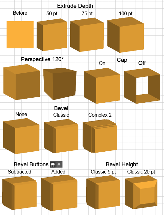
) in the row of bevel-related parameters:
      1. The first (fat) button, the Bevel Extent Out button, makes the bevel appear to be added onto the virtual 3D object.
      2. The second (skinny) button, Bevel Extent In button, makes the bevel appear to be carved away from the virtual 3D object.
Creating Depth with Revolve

This article also contains the detail for Step 7 of the General Method for Applying 3D Effects.

The Revolve process for creating the appearance of depth, works by virtually revolving a 2D path around its right or left edge, which then takes on the appearance of being a line of 3D axial symmetry that runs along the y-axis. The process can create two, related but topologically different, kinds of 3D figures:

Screen shot of

Counterclockwise rotation through 230° around the left edge of the 2D figures, producing a cutaway view of a virtual tube and cylinder.

  • A tube-like structure with a hole through the y-axis, which is achieved by rotating a closed 2D figure around an axis from which its right or left edge is offset, and
  • A cylinder-like structure, with no central hole, which is achieved by rotation an open 2D path directly around the axis of rotation (with no offset). In this case the 2D path typically has the form of half of the outline of the 3D figure.


For either type of rotation, you can set parameters that:

Screen shot of
3D Rotate Options Dialog
  • Set the rotation to less than 360 degrees, which will give the structure a cut-away appearance.
  • Make the front face transparent so that you can see inside the 3D structure.

To Create Depth with the Revolve Effect in Adobe Illustrator:

  1. To make a tube-like figure with a vertical hole through it, set the Offset field to the radius of the hole.
  2. To make a cylinder-like figure with a vertical hole through it, set the Offset field to 0.
  3. To make a solid tube or a solid cylinder, set the Angle field to 360 degrees. To create a cut-away figure, set the angle to 360 degrees minus the size of the angle that should be cut away.
  4. To make the front face (the face that is blue on the Tracking Cube) empty, so that you can see into the cube, set the Cap to no cap.
  5. To make Ai generate the 3D figure by rotating the 2D shape around its right edge (instead of the Left Edge, the default) go to the from dropdown field and select Right Edge.
Choosing the No Cap option makes the 3D structure look hollow.
Screen shot of

Counterclockwise rotation through 230 around the RIGHT edge of the 2D figures.

Specifying 3D Orientation
Screen shot of
3D Orientation Dialog Options

This article contains the detail for Step 8 of the General Method for Applying 3D Effects.

The Tracking Cube: Controls the orientation of the figure's virtual x, y, and z axes:


  • The X-axis (the direction of the red edges on the Tracking Cube) is the apparent horizontal, i.e., width dimension of the 3D figure.  Updating the top numerical field controls rotation about the X-axis.
    Illustration of Tracking Cube Dimensions
    Tracking Cube Dimensions
  • The Y-axis (the direction of the green edges on the Tracking Cube) is the apparent vertical, i.e., height dimension of the 3D figure. Updating the middle numerical field controls rotation about the Y-axis.
  • The Z-axis (the direction of the blue edges on the Tracking Cube) is the apparent depth dimension of the 3D figure, which extends into the x-y-plane. Updating the bottom numerical field controls rotation about the Z-axis.

On the Tracking Cube, the blue face is the front (x-y) face. The dark gray face is the side (y-z) face. The light gray face is the top (x-z) face.  

Illustration of How to Rotate a 3D Figure with the Tracking Cube
How to Rotate a 3D Figure with the Tracking Cube

To set the Orientation of the 3D figure in Adobe Illustrator do the following:

  1. To rotate the figure around one of the 3 axes, hover the cursor over an edge of the Tracking Cube. Ai will change the edges' color to show you what axis you will rotate around. 
    1. Grab a red edge to rotate around the X-axis.
    2. Grab a green edge to rotate around the Y axis.
    3. Grab a blue edge to rotate around the Z-axis.
  2. To control the rotation around an axis quantitatively, enter a value between +180 or -180 degrees in one of the fields.
  3. To add perspective to the figure, enter a value from 0 to 160 degrees in the Perspective field.
  4. To use Orientation Presets rather than manipulating the Cube or entering parameter values, select an entry in the Position dropdown list.
Specifying 3D Surface Properties and Lighting
Illustration of 3 Standard Lighting Effects3 Standard Lighting Effects

This article contains the detail for Step 9 of the General Method for Applying 3D Effects.

To specify 3D surface and lighting options in Adobe Illustrator:

  1. In the Surface field, select an option for the type of surface. Diffuse shading makes the shading darker than the fill, with no highlights.  Plastic shading makes Ai add highlighting and enables the Highlight Intensity and Highlight Size fields.
  2. In the area of the dialog box with the shaded sphere, shown in the accompanying diagram, create the light sources and position them:
    1. To create a new light source, click the plus-sign (+) button. Ai will add a light source icon to the sphere.
    2. Move the light-source icon so that it illuminates one or more if the figures virtual surfaces. You can add as many lights as you need.
    3. To place a light in back or behind the 3D figure, select the light icon, and click the first icon under the sphere. This creates a ridge of light that wraps around the figure's edges, and is useful for getting rid of overly dark shadows.
  3. Adjust the Light Intensity of each light source:
    1. Select the light source icon.
    2. Update the percentage value in the Light Intensity field.
  4. Update the Ambient Light field to control the general level of light-dark contrast.
  5. Update the Highlight Intensity field to control how much brighter the highlights look from their surroundings.
  6. Update the Highlight Size field, to control how much area the highlights occupy on the surface.
  7. Update the Blend Steps field to eliminate banding and make the lighting difference appear smooth and continuous.
  8. In the Shading Color dropdown, select the Custom option to define a custom shadow color.
Map Art
Screen shot of
Example of the Map Art functionality, showing the 2D path, the 3D object that results from the Revolve Effect, and the Symbol with the art to be attached to the 3D Surface.

You can attach art (text, images, or both) to 3D appearances that were created with the Extrude and Bevel Effect or with the Revolve Effect.

To place art on a 3D virtual surface in Adobe Illustrator:

  1. Convert the art to a static symbol.
  2. In the 3D option dialog box, click the Map Art Button. Ai will display the Map Art dialog, which (A) allows you to select surfaces of the 3D object to which you can attach the art, and (B) shows a flattened 2D view of the selected virtual surface.
  3. Click the Surface paging controls to page through the available surfaces. In the 2D view, the light areas represent parts of the surface that are visible on the 3D object in its current orientation.   Dark areas represent areas that are not currently visible in 3D. On the Art Board, Ai will switch to a wire-frame view and highlight the currently selected surface in red.
  4. In the Map Art dialog, select the surface to which you want to attach the surface art.
  5. From the Symbol dropdown Select the symbol.
  6. Position the Art on the visible (light) area of the 2D view of the selected virtual surface.

Illustration of selecting the 3D surface to which to map the Art.

Selecting the 3D surface to which to map the Art.
Rotate Effect

The Rotate Effect does not add a depth dimension, it merely gives a 2D object the appearance of existing in 3D space. Specifically, the Effect places the 2D object in the same 3D orientation as the front (blue) face of the Tracking Cube.

Therefore, unlike the Extrude and Bevel Effect or the Revolve Effect, the Rotate Effect does not have a section of its Dialog box devoted specifically to creating depth. The only controls available for the Rotate Effect are those for Orientation and Lighting.

You cannot Map Art with the Rotate Effect, but you can apply the Rotate Effect to:

  • Point text or blocks of area text (as in the accompanying example.
  • Images.
  • Groups that contain both images and text.

As an illustration of how the 3D Rotate Effect mimics the position of the Cube's blue face, note that (as shown in the accompanying figure), if you rotate a block of text so that the blue face is in the back, the Tracking cube, text will be reversed.

The following example shows that applying the Rotate Effect to text makes both the shape of the block and the text itself take on the shape of the front, blue face of the Tracking Cube.

Convert to Shape

The utility of the Convert to Shape Effects follows from two Illustrator capabilities:

  • Paths can have more than one fill or stroke, and
  • Convert to Shape Effects apply to Fills and Strokes.

You can use these capabilities to create backgrounds for paths, including text objects.

Number Callouts Example
Illustration of How to
A number with a second red fill added is converted into a red circular background to make the number into a call-out

As an example of the power of Convert to Shape Effects, you can convert text characters into number callouts by giving the text a second fill and using the Convert to Shape Effect to change the extra fill into an ellipse, rectangle, or rounded rectangle.

To convert editable number text characters into a number call-out: in Adobe Illustrator:

  1. Create the text for the number and select it.
  2. Execute the command Effect > Path > Outline Object. Ai will hide the Bounding Area, which will help center the number vertically.
  3. Add a second fill. Choose a color that you want to be the background color of the call-out.
  4. Target the fill.
  5. Execute the command Effect > Convert to Shape > Ellipse. Ai will open the Shape Options dialog box.
  6. In the dialog box, select the Absolute Size option, enter a Width and Height, and click OK.
Illustration of Text with several fills converted to form a background
Text with several fills converted to form a background

Here is a more complex example:

The accompanying figure shows a text object with a black fill and no stroke.  The background was constructed as follows:

  • Give the text 3 additional fills. 
  • Apply two effects to each fill in the following way:
    • Execute the Effect > Convert to Shape > Ellipse command to convert the fill into a circle.
    • Execute the Effect > Distort and Transform > Transform command to offset the circle to the positions shown.
  • In the Appearance panel, adjust each fill's opacity (set to 33% in this example) and set the blend mode (to Difference in this example).

Distort & Transform

Zig Zag and Roughen
Illustration of How to
How the Distort and Transform Zig Zag and Roughen Effects work

The Zig Zag and Roughen Effects, which have similar properties, provide an example of how Distort and Transform Effects work. This example applies the Effects to simple lines and illustrates that these effects become more interesting when applied to other dynamic technologies such as Stroke Width Profiles.

Both of these Effects are controlled by 4 analogous parameters, which are displayed in each effect's dialog box.

  • Size field and slider.
  • Relative or Absolute radio button group. If you specify Relative, the Size field units will be percentages relative to the size of the object to which you have applied the Effect.  If you select Absolute, the size units will be in the document's units, e.g., pixels.
  • Ridges per segment field and slider for Zig Zag (or the Detail parameter for Roughen, with units in kinks per inch).
  • Smooth or Absolute radio button group.

To use the Zig Zag and Roughen Effects in Adobe Illustrator:

  1. Draw the object to which you want to apply the effect. Be aware that if you select the Relative radio button, the extent of the effect will scale with the size of the object.
  2. Execute the Effect > Distort & Transform > Zig Zag command (or the Effect > Distort & Transform > Roughen command). Ai will open the Zig Zag (or Roughen) dialog box.
  3. In the dialog box, turn on the Preview checkbox. Then specify the parameters that control the Effect's the size, the units of the size, the frequency of the effect, and whether the changes (points) should be smooth or pointed.
  4. Click OK
Transform Effect

Here is an example of the Transform Effect that is adapted from Ste Bradbury's tutorial on drawing Geometric Line Art (at Ste Bradbury Design). The example highlights the Effect's capability to both generate multiple copies of an object and to scale those copies. The result resembles a set of nested Russian matryoshka (little matron) dolls where each copy contains another smaller copy.

Illustration of How to
Name

To construct this example in Adobe Illustrator:

  1. Draw the object to which you want to apply the effect.
  2. Execute the Effect > Distort & Transform > Transform command. Ai will open the Transform dialog box.
  3. In the dialog box, turn on the Preview checkbox.
  4. Reduce the horizontal and vertical scale from 100% to a smaller number. The amount of reduction will determine the amount that each copy will shrink relative to its predecessor. With the Preview enabled, you can experiment with different combinations of settings by placing the cursor in any numerical field and tapping the up and down arrow-keys to increment or decrement the values, one unit at a time.
  5. Increase the number of copies.
  6. Increase the Rotate Angle by a few degrees.
  7. Click OK
Free Distort

Here is an example by Dansky that illustrates how the Free Distort Effect works when applied to a Group that contains several lines of Point-Text. Note that the Effect distorts the contents of the group in direct proportion to the distortion of the boundary that you set in the Free Distort dialog box, which gives the characters the appearance of being twisted in perspective.

Path Effects

Illustration of Illustration of the Path Offset Effect applied to the fill, the stroke and the path itself
Path Offset

The Path Effects category contains 3 Effects:

  • Offset Path gives a path's stroke, fill, or the path a virtual offset (relative to the real path).  This effect is a nondestructive option to using the Object > Offset Path command.
  • Outline Object gives the non-transparent portion of a raster object a virtual outline or a silhouette. 
  • Outline Stroke produces a virtual appearance that is analogous to executing the Object > Path > Outline Stroke command, which converts an open path into a closed path with a fill and no stroke. For text, this effect acts like the Type > Create Outlines command.
Illustration of How to
Outline Stroke

The accompanying figure shows that applying the Outline Stroke Effect to paths before applying Pathfinder Effects dramatically changes the result. Pathfinder Effects apply to Groups of objects. When you apply the effect, the objects in the Group are combined in a way that is analogous to the operations in the Pathfinder panel, except that all the Effects remain modifiable, reversible., non-destructive and the original paths remain editable.

To apply Pathfinder Effects to a Group that contains overlapping open paths with strokes but no fills, you must first apply the Outline Stroke effect to the paths inside the Group. That will make them appear to be closed paths that have a fill but no stroke. Essentially, you are telling Ai: pretend that the stroked paths are shapes. Then, when you apply the Pathfinder effect to the Group, Ai will combine them as though they were filled closed paths.

Offset Path Command: Place an Outline around a Group of Objects
Illustration of How to Add an offset outline around a Group of Objects
Add an offset outline around a Group of Objects

To create an offset outline around a group of objects in Adobe Illustrator:

  1. Select the Group and add a stroke to it. Ai will add the stroke to each object.
  2. With the group selected (in the Layers panel), target the new Stroke in the Appearance panel). Ai will highlight the stroke's row in the appearance panel.
  3. Execute the Effects > Path > Offset Path command.  Ai will offset the stroke on each object.
  4. With the new stroke still selected, execute the Effect > Pathfinder > Add command. Ai will unite the borders into a single border.
Offset Path: Place an Offset Outline around Text
Screen shot of Offset Path around Text
Offset Path around Text

To create an offset outline around text in Adobe Illustrator:

  1. Select the text. Ai will display the text’s Type object in the Appearance panel.
  2. In the Appearance panel, target the Type row.
  3. Go to the bottom of the Appearance panel and add a stroke. Ai will add the stroke to each character.
  4. In the Appearance panel, target the new stroke.
  5. Execute the Effects > Path > Offset Path command. Ai will offset the stroke from each character.
  6. Execute the Effect > Pathfinder > Add command. Ai will unite the offset strokes into a single stroke.
Outline Path: Add an Outline to an Image
Illustration of How to
Add a "shadow" outline to an image.

You cannot simply apply a stroke to an image that you place in an illustrator file, but you can create a border around the visible part of an image via the Effect > Path > Outline Object command sequence. However, before you can use the Effect you must create a Stroke row in the Appearance panel so that Ai has an attribute to which to apply the appearance.

To add an outline to the non-transparent portion of an Image in Adobe Illustrator:

  1. Target the image.
  2. Go to the bottom of the Appearance panel and add a stroke. Ai will add a row in the appearance panel but will not apply a stroke to the object.
  3. Set the stroke's width and color.
  4. With the new Stroke's row selected in the Appearance panel, execute the Effect > Path > Outline Path command. As shown in the figure, Ai will add a virtual shape that extends outside and around the non-transparent portion of the image.
Outline Stroke: Align Text Vertically in a Shape
Illustration of How After applying the Outline Stroke effect, the Bounding Box hugs the text.
After applying the Outline Stroke effect, the Bounding Box hugs the text.

When you align text with the Align panel, Ai actually aligns the Bounding Area, i.e., the area covered by the Bounding Box. In the case of Type objects, it includes the space below the base line that is included for the text's descenders. This can make vertical alignment inaccurate. You can improve the alignment accuracy by using the Outline Stroke effect to shrink wrap the Bounding Area to the text.  As explained above, when you apply the Effect > Path > Outline Stroke effect, Ai turns the strokes into virtual shapes.

To center text vertically within a path in Adobe Illustrator:

  1. Target the text.
  2. Execute the Effect > Path > Outline Stroke command. Ai will shrink-wrap the Bounding Area around the text.
  3. Select both the path within which you want to vertically center the text and the text itself, and then click the path again. That will make the path the key object.
  4. Go to the Align panel and click the center vertically button. Ai will move the text so that it aligns to the key object, the path, which will remain stationary.

Pathfinder

The results of applying many of the Pathfinder Effects look similar (but not identical) to the Pathfinder Panel operations. However, the Pathfinder Effects do not change the structure, but only the appearance of objects that the Effects combine.

Also, in contrast to Pathfinder Panel operations, you cannot apply Pathfinder Effects directly to the component paths.  Before applying the effect, you must group the components and apply the Effect to the Group.

Note

The Ai documentation also describes the result of Alt + Clicking one of the Shape Mode buttons in the top row of the Pathfinder panel as an effect. However, while the result is non-destructive, modifiable, and reversible, it does not produce an object that has an fx row in the Appearance panel.

Apply a Pathfinder Effect
Illustration of How Pathfinder Effects look in the Appearance Panel
How Pathfinder Effects look in the Appearance Panel

To apply a pathfinder effect in Adobe Illustrator:

  1. Group the objects.
  2. Apply the effect (Effects > Pathfinder and then select the effect). Ai will apply the Effect, which will virtually combine the objects.
  3. Optionally, click the effect in the Appearance panel to open the Pathfinder Options dialog, from which you can modify the Effect.
  4. Optionally, to convert the Effect into real paths that have the same appearance, execute the Object > Expand Appearance command. Ai will replace the appearance, i.e., the virtually combined objects, with real paths that actually and permanently combine the objects.

Pathfinder Effects Comparison

Illustration of How to

Stylize Effects

The Scribble Effect's virtual line.
How the Scribble Effect Scribbles when applied to a red fill.

As discussed above, most of the Stylize Effects are raster Effects, only the Round Corners and Scribble Effects are genuinely, vector Effects. The Round Corners Effect is of limited value now that the Live Corner Widget facility is so advanced, easy to use, and is also non-destructive, modifiable, and reversible. That leaves the Scribble Effect as the only Stylize Effect that is interesting here.

When applied to the target object, one of its fills, or one of its strokes; the Scribble Effect changes the object or attribute to which it is applied into a single virtual path with a virtual stroke. The color of the real object, fill, or stroke determines the color of the virtual path's virtual stroke. The virtual path oscillates across a fill or stroke of the target object in a way that is prescribed by 9 parameters.

Example of how the Scribble Effect Variation Settings Work

In the dialog box, you can set the following parameters:

  • Settings, a dropdown of preset options.
  • Angle of the scribble path from -179 to 180.
  • Path Overlap i.e., the number of pixels by which the scribble lines can exceed their boundary.
  • Variation i.e., the number of pixels by which the Path Overlap can vary.
  • Options that determine the virtual stroke that the Effect will apply to the virtual path of the scribble path, which define the properties of the scribble line, including:
    • Stroke Width, i.e., the width in pixels of the virtual stroke.
    • Curviness of the path expressed as a percentage of the Stroke Width.
    • Variation of the Curviness among lines, expressed as a percentage.
    • Spacing, i.e., the number of pixels between Strokes.
    • Variation of the Spacing among lines, expressed in pixels.

You can apply Scribble to:

  • Open paths with one or more strokes.
  • The individual fills and strokes of closed paths.
  • Text.
Applying the Scribble Effect
Illustration of How to
Stylize Scribble Effect

To apply a Scribble Effect in Adobe Illustrator:

  1. Select the object.
  2. In the Appearance panel, target the object, or for closed paths, the entire object or any of its fills or strokes individually.
  3. Execute the Effect > Stylize > Scribble command.  Ai will open the Scribble Options dialog box.
  4. Check the Preview checkbox.
  5. Adjust the options via the sliders or by placing the cursor in the number field and pressing the up or down arrow keys.
  6. Click OK.

Warp

The 15 Warp Effects all share the same Warp Options dialog box and the same parameters. When you apply one of the 15 Warp Effects, to a target object, the Effect makes the target look like an object that has the shape of the style that is associated with that effect. You can then use the other Option Dialog box parameters to modify the basic style by bending or distorting it horizontally and vertically in percentage increments.

Here is an illustration that lists and compares the Warp Effects.

Illustration of the 15 Warp Effect Styles

The Wave, Fisheye, and Twist Effects are special; they behave as expected only if:

  • You apply them to a container (a Group or a Layer, and
  • The container contains two objects, and
  • Screen shot of
    Perspective Distortion
    One of the objects in the container is both on top of and inside of the other.  Then the Effect will apply to, but only to, the topmost (inside) object in a Layer or Group.

When you apply the Wave, Fisheye, and Twist effects, to a single object, the Vertical Distort dialog box parameter applies and produces a perspective effect.

Using a Warp Effect
Warp Options Dialob Box
Warp Dialog Box

To use a Warp Effect in Adobe Illustrator:

  1. Select the object to which you want to apply the Warp.
  2. In the Appearance panel, select the entire object (the top row) of one of the rows for a fill or a stroke.  
  3. Execute the command Effect > Warp > X, where X can be any of the 15 Warp Effects. Ai will open the Warp Options dialog box.
  4. Check the Preview checkbox.
  5. Optionally, use the Style dropdown to preview any one of the 15 Warp Effects.
  6. Choose the parameters for:
    1. The Bend direction (Horizontal or Vertical).
    2. The Bend percentage amount, and.
    3. Optionally, the Horizontal Distortion percentage and
    4. Optionally, the Vertical Distortion percentage.
  7. Click OK
You can adjust basic shapes by distorting them distort vertically or horizontally.
Distortion Effect Warp
Warp effects are commonly used on text, often as visual containers.
Warp Effects applied to text.

Resources